
 I needed to quantify volumetric water content for a water stress experiment I have going in the greenhouse, but jeez, even a relatively simple setup can cost a pretty penny ($300 -$500). So I went the DIY route.
You don’t want to skimp on quality for the actual sensor — for repeated insertion in greenhouse or field soil, you’ll want stainless steel probes and (relatively) weatherproof housing, and as always, we’re after high resolution and accuracy. I went with the recently released Decagon GS-1, which will set you back $114. It’s advertised as also being able to minimize any salinity and textural effects of your soil, which can throw off VWC readings.
But once you have the actual sensor, all you really need is a device to measure voltage via the sensor cable. What we’re doing is getting an indirect measure of soil moisture content by seeing how “easily” an electromagnetic wave can pass through our soil medium; the amount of liquid water in soil changes this property in a predictable manner. (Go here to read more about soil dielectric constant). And to measure voltage we can head down to the local hardware store and pick up a multimeter for less than $30!
What you’ll need:
- Standard 9v battery
- 9v battery housing
- Soil moisture sensor (I used the Decagon GS1)
- Note: if you use a sensor other than the GS1, you’ll need to contact the manufacturer’s tech support to see how much voltage your power source (in my case, the 9v battery) needs to supply. The GS1 has a voltage regulator housed in the sensor; it can handle from 3 – 15 volts
- Multimeter (something like this one) that can measure DC voltage
- Electrical tape
- Small wire connectors (wire nuts)
- Wire stripper
- Cable ties
Assembly:
I apologize for the dearth of instructive photos in this tutorial — the next DIY post will be better documented.
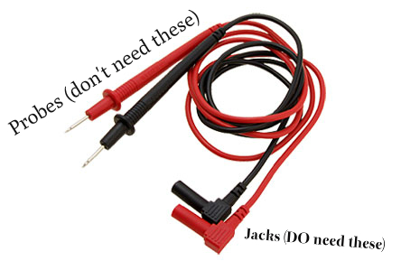
- Cut the black (common) and red (live) leads that came with your multimeter to the length you want them; I’d suggest about 8 inches long. You need the ends that have a “jack” — these plug into the multimeter. You’re just getting rid of the “probe” ends. You need to access the bare wires to make the necessary connections to the other hardware. (You could read voltage without hardwiring everything together, but I prefer to have everything in one portable unit.)

Multimeter leads - Cut your soil moisture sensor wire to an appropriate length for your purpose (i.e., you need it long enough to move around freely, but not so long that it’ll get in the way).
- If your 9v battery housing wires have plugs at their ends, snip those off, too. You need to get at the bare wire.
- Strip about 1/2″ of the insulation off the end of each freshly cut wire using a wire stripper.

Strip wires ~1/2″ - Now to make connections. Make sure the battery is NOT in the housing, and that the multimeter leads are NOT plugged into the multimeter.
- Here’s a mildly confusing photo showing the wire connections. I’ll try to explain things clearly in the text.

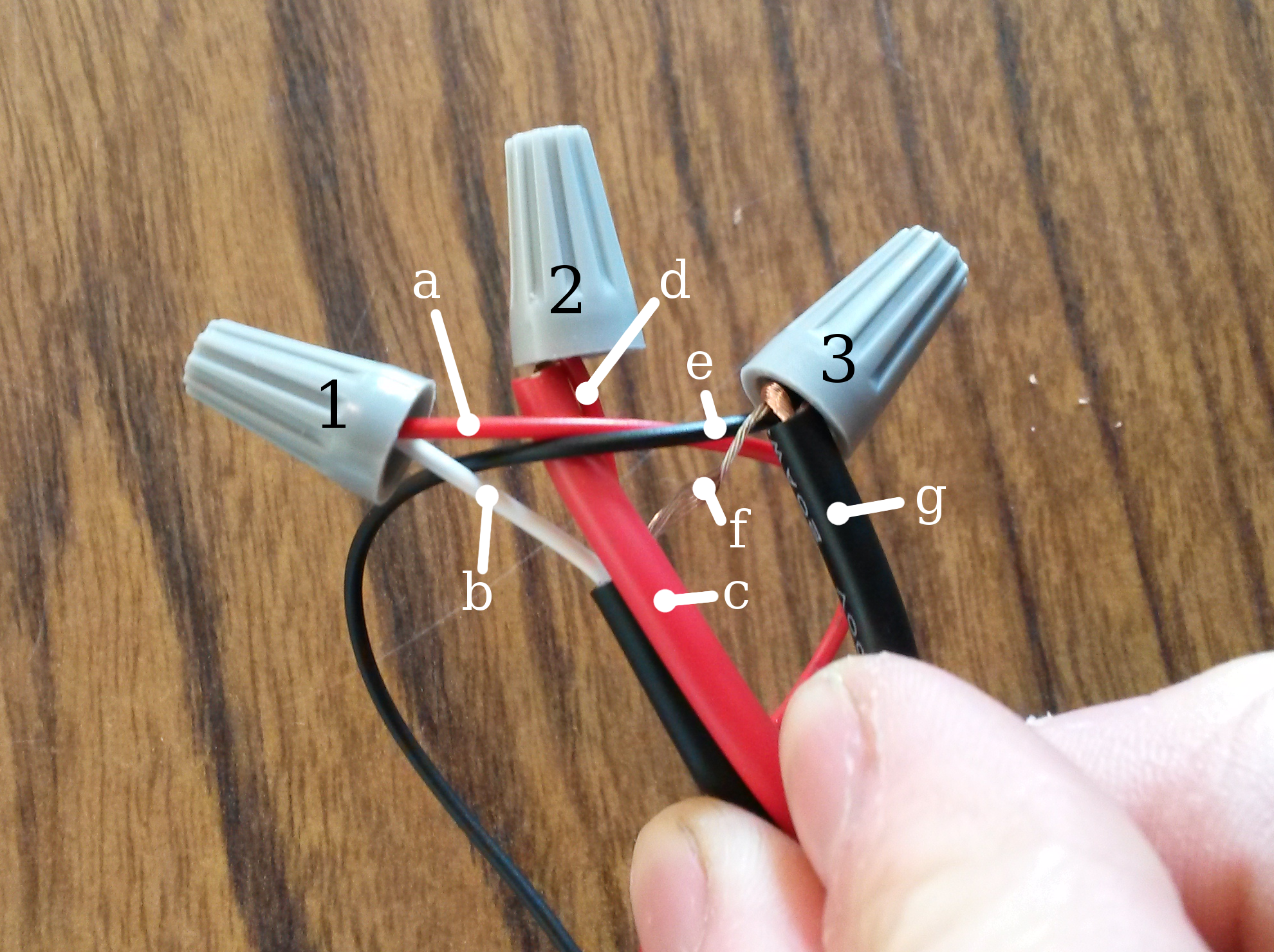
1 = red battery positive (a) + white VWC sensor power wire (b); 2 = red multimeter live lead (c) + red VWC sensor data wire (d); 3 = black battery negative (e) + bare VWC sensor ground wire (f) + black multimeter common lead (g) - We’re making three main “hubs”, labeled in the photo as 1, 2, and 3. Use wire nuts to secure all connections.
- Hub 1 is comprised of:
- the positive wire from the battery housing (usually red) (a)
- the power wire from the VWC sensor (which is white on the GS1) (b)
- Hub 2 is:
- the live lead from the multimeter (usually red) (c)
- the data wire from the VWC sensor (which is red on the GS1) (d)
- Hub 3 is:
- the negative wire from the battery housing (usually black) (e)
- the ground wire from the VWC sensor (which is bare on the GS1) (f)
- and the common lead from the multimeter (usually black) (g)
- Hub 1 is comprised of:
- Here’s a mildly confusing photo showing the wire connections. I’ll try to explain things clearly in the text.
- After making all connections, secure each hub with electrical tape. I also taped up all three hubs together, just to keep things nice and neat. Use the cable ties to tidy up further.

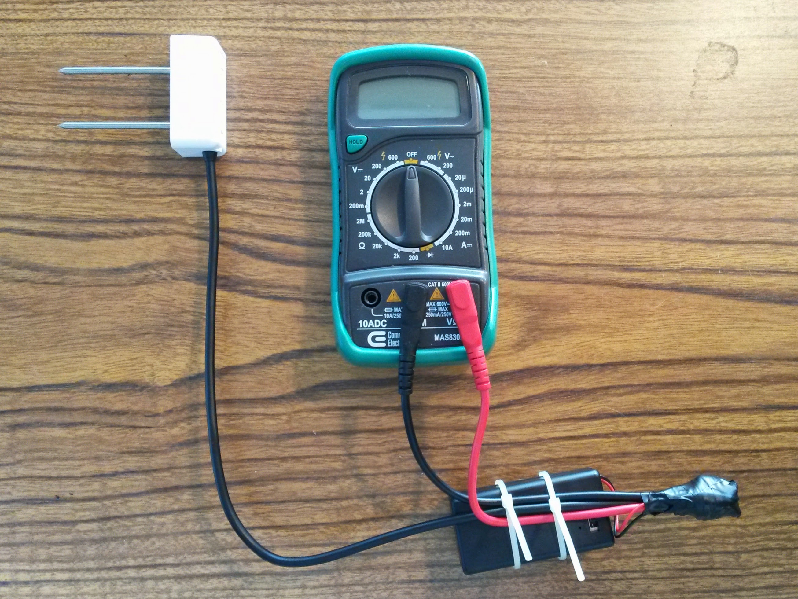
DIY VWC Sensor - Install your 9v battery in the battery housing.
- Plug your leads into the multimeter. Black goes to common (usually COM) and live / red goes to the voltage jack.
- If your battery housing has an “on / off” switch, be sure it’s switched to “on”.
- Turn the multimeter dial to read DC voltage (which is usually a V beside a bar with dots underneath). For the GS1, I read at the 2V setting, which gives me output in volts to the nearest thousandth. Convert your reading to mV, then use the appropriate conversion equation (for the GS1 it’s VWC = 4.94 x 10⁻⁴ x mV – 0.554) to find VWC.
For the GS1, you need to make sure the sensor probes are ALL the way in the soil when you take your measurement; if there’s a gap it can throw the readings off. Also, I usually let the multimeter equilibrate for 5 seconds or so before recording the reading.
Happy tinkering!
